IPhone 13 Pro Max Black Screen does Not Turn On Repair
[Machine model]
iPhone 13 Pro Max
[Fault Phenomenon]
I received an iPhone 13 Pro Max with a black screen and did not turn on. According to the customer's description, it stopped charging after plugging in the OTG data cable, and then automatically shut down and could not be turned on. I took it to a nearby repair shop, but it wasn't repaired, so a colleague forwarded it to us.
【Maintenance process】
When I received the phone, according to the previous description, only U2 and the charging chip were replaced, and other parts were left unchanged; I looked at the motherboard, and luckily it was not repaired in a messy way.
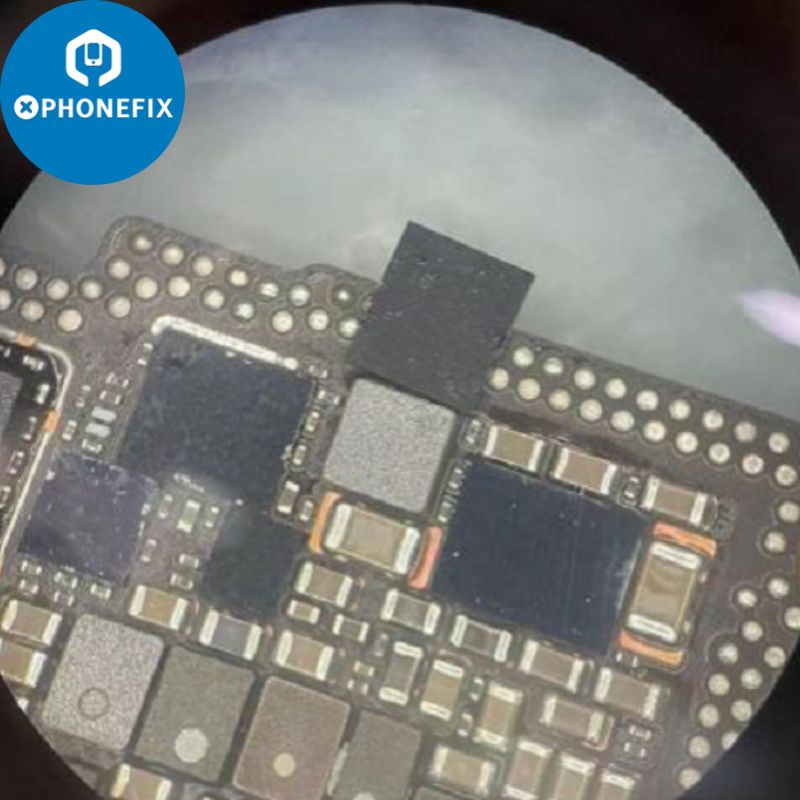
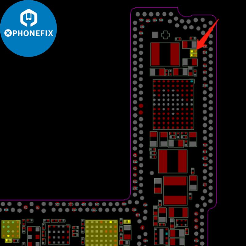
The most burned out external devices that Lenovo had repaired before were the ACC accessory identification chips. I opened the Xinzhizao software and judged based on the bitmap that the accessory identification of the iPhone 13 Pro Max was in the shielding cover. After cutting the shielding cover, I found that the ACC accessory identification chip was in the shielding cover. The inductor of the chip has been broken down. After replacing the chip and inductor, I measured the surrounding capacitance and found that there was no short circuit. The installation test fault remained the same.
At this time, the motherboard was layered to measure the 5V power supply of the USB until it reached the charging chip. It was found that the 5V power supply was only 4.8V. After replacing the rear case assembly, it was still only 4.8V. That was a problem with the motherboard. The previous company had replaced the charging chip and reinstalled it. The fault remains.
After directly replacing a chip, the 5V was no longer pulled down, and the battery holder also had 3.6V. It still did not charge during the test.(JC V1SE battery Flex Cable)
Use phonefix's Fluke 18B+ multimeter high-precision temperature frequency automatic multi-function digital multimeter for mobile phone repair.
After entering the system from the upper layer, I looked at the battery data. The battery had been replaced and I could not see it. I connected the computer to see the battery data but could not get online. Since I was not online, I directly replaced a USB chip and the test fault remained the same.
I replaced another 13PM battery with 80% charge to eliminate the battery problem.
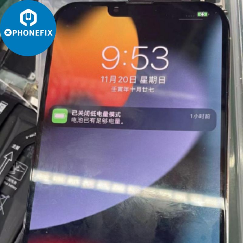
At this time, I found that the power displayed by the machine was also very low. I measured the resistance of the battery detection pin as if there was no battery data. Sure enough, I found a problem. The normal machine should be more than 500, but here only more than 200 is obviously lowered.
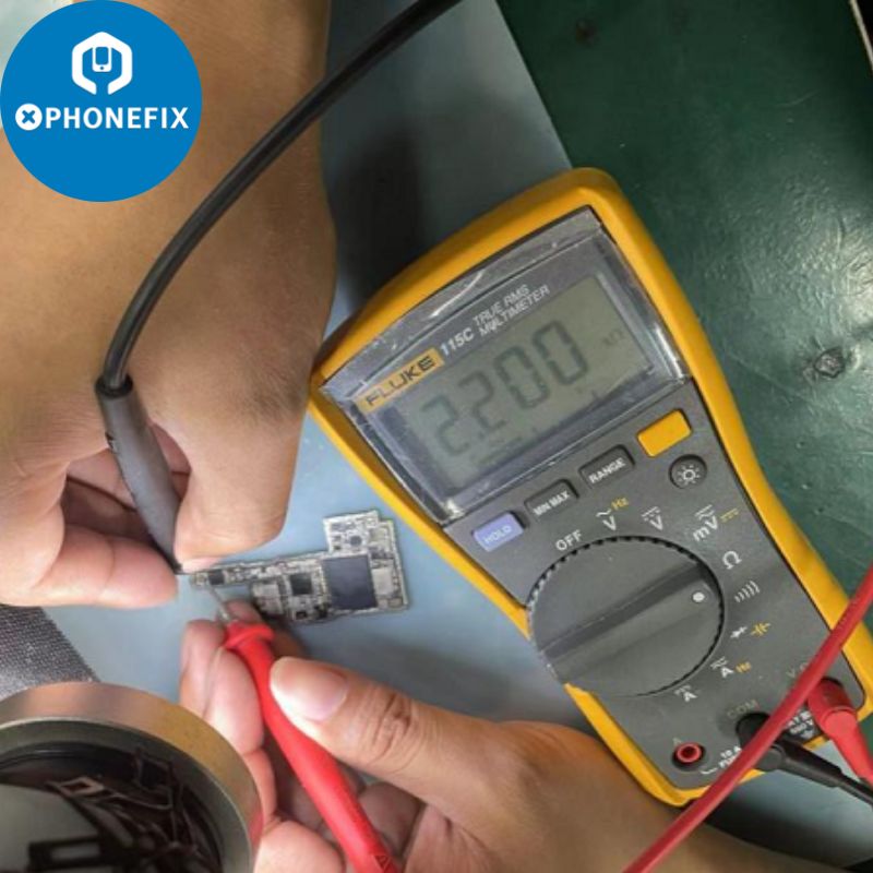
According to the bitmap, it is found that this pin is connected to a resistor. After checking that there are many chips connected to the other end of the resistor, it is judged from experience that it should be a pull-up resistor. The multimeter is adjusted to the ohm range and the measurement finds that it is only 2 ohms.
Find a normal board and measure the resistance to make sure it is 2.2K ohms.
I found an I2C pull-up resistor from a 6th generation board and installed it. The resistance of the test pin was over 500 and it was normal. I installed the single upper layer into the case to see if charging current could flow. Then I re-soldered the motherboard and put it back together and tested. Charging is normal.


Comments
Post a Comment